AL G8
All external units are connected to the main unit (interface box) by RJ25 connector - marked as S. Control wires are using connector RJ45 - connector marked as C.
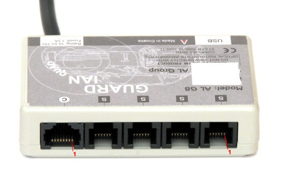
RJ25 pinout - marked as S
| Pin number | Pin functionality |
|---|---|
| 1 | Ground |
| 2 | Output of pulses for transmitter(5V CMOS) |
| 3 | Park assistant output (5V CMOS) |
| 4 | Supply +30V |
| 5 | Input of receiver pulses (5V CMOS) |
| 6 | Ground |
All pins (except pin5) are connected paralelly in the interface box. Pins 5 are connected via Schottky - diodes SS16.
All outputs are lacking any overcurrent/overvoltage protection.
RJ45 pinout - marked as C
| Pin number | Pin functionlity |
|---|---|
| 1, 2 | Output for dual-color LED |
| 3 | Ground |
| 4 | MUTE output |
| 5 | Push-button (switched to ground) |
| 6 | Beeper (second input of beeper goes to ground) |
| 7, 8 | Power supply switch |
Internal pictures of the interface box
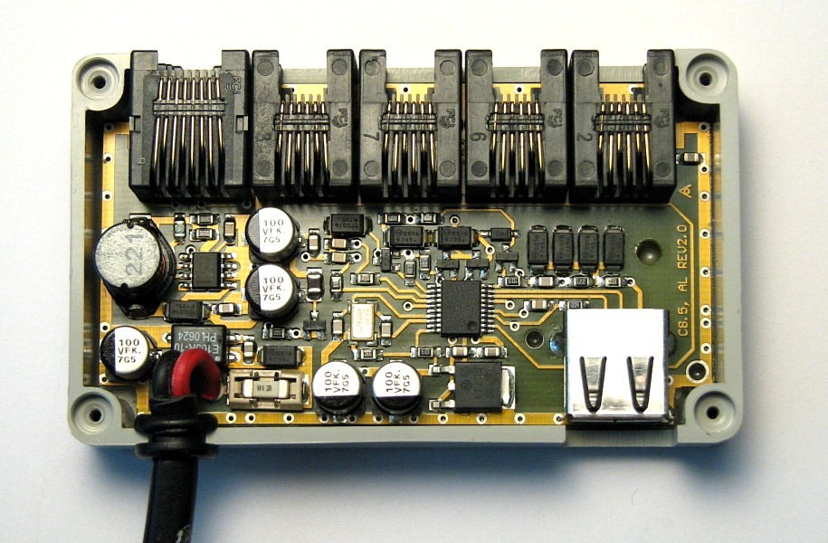
In the left part there is power supply filter and step-up convertor (to 30V using MC33063) for external units. Main microcontroler PIC16F648A running at 20MHz is in the middle.
Author of these pages takes NO RESPONSIBILITY of any damages nor expenses caused by supplied informations.